Products

Analysers and sensors

The instruments that perform the measurement: portable performance analysers, cylinder pressure sensors, and acoustic emission sensors for extended diagnostic coverage.

Instrumentation

Two instruments, one measurement chain

DieselScope, a full performance analyser for complete combustion and engine analysis, and DS Compact, a compact unit for rapid peak-pressure checks and in-situ tuning. Both use Kistler pressure sensors, both suit any two-stroke or four-stroke engine fitted with indicator valves, up to 20 cylinders, and both are read by the same analysis software.

Both instruments are available as OEM solutions under a customer’s own brand, and both are repaired and calibrated in our workshop.

DieselScope — portable performance analyser

A stand-alone instrument with its own processor, carrying out calculation and analysis on board without a laptop. There are no junction boxes and no fixed power or signal cabling: the unit is carried from engine to engine, and from vessel to power station or test bed.

  • Backlit display of 320 × 240, with pressure–angle diagram, cursor and zoom
  • Bar plots in absolute values and as percentage deviation, and a per-cylinder table summary
  • Averaged measurement for scheduled records, or live output for tuning and balancing while the engine is adjusted
  • Storage for 30 engines and 60 measurement records
  • Rechargeable battery, 20 hours between charges
  • Optional fuel injection kit for recording injection events, and a signal simulator for verifying instrument integrity
  • The DS Acoustic extension adds acoustic emission measurement alongside cylinder pressure
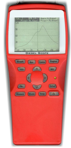
The DieselScope handheld analyser, showing a pressure–angle trace on its display.
The DieselScope handheld analyser.

DS Compact — mini indicator

A metal handheld unit operated with two buttons, for engineers who require maximum cylinder pressure quickly and without configuration. In its simplest use it serves as a maximeter; with a TDC sensor fitted it provides the crank angle data required for full analysis.

  • Four-digit display showing engine selected, maximum cylinder pressure and engine speed
  • Automatic detection of engine speed and TDC
  • Storage for 18 engines and 125 cylinder measurements in non-volatile memory
  • Up to 10 hours between charges on standard AA cells, recharged over USB
  • Analysis software loaded from the instrument itself when it is first connected to a PC
  • Deviation limits set centrally, so sister vessels with the same engines are assessed against the same targets
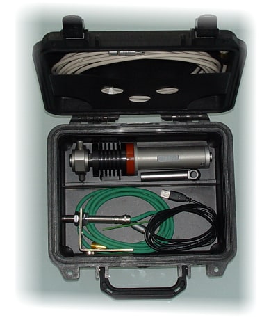
DS Compact carrying case, with sensor and cable accessories.
DS Compact carrying case.

Recorded and derived

  • Maximum combustion pressure, compression pressure and expansion pressure, per cylinder
  • Full pressure–crank angle and pressure–volume diagrams
  • Mean indicated pressure, indicated power and cylinder load balance across the engine
  • Angle of ignition, ignition delay, injection delay and injection duration, against reference values
  • Engine-level values including specific fuel oil consumption, engine and turbocharger speed, scavenging pressure and exhaust gas temperature

Both main engines and auxiliary sets are covered, across two-stroke crosshead and medium-speed four-stroke machinery, up to 20 cylinders per engine. The requirement is an indicator valve: any engine fitted with one can be measured, and any engine without one cannot. Engine reference data is held in a library on the instrument, so measurements are assessed against the correct layout for the engine concerned.

Referencing top dead centre

The instrument records 3600 points per engine cycle: one crankshaft revolution on a two-stroke, two revolutions on a four-stroke. That is a resolution of 0.1° on two-stroke engines and 0.2° on four-stroke, which allows injection timing and ignition delay to be determined rather than merely estimated. Three sensor types cover the range of installations.

Sensor Installation Mounting gap
OpticalPortable50–300 mm
InductiveFixed2–4 mm
MagneticFixed5–10 mm

A fixed sensor is recommended for slow-speed two-stroke engines, where sufficient data points are needed to establish crank angle reliably. On four-stroke engines a portable optical sensor is usually sufficient, though a fixed kit is advisable where ignition occurs before top dead centre and the centre of the compression curve cannot be used to derive TDC.

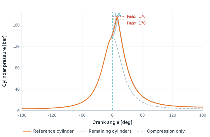
Pressure–angle diagram for a six-cylinder engine, all cylinders overlaid, peak pressures between 170 and 176 bar shortly after top dead centre, with the compression-only curve for comparison.
Pressure against crank angle, all cylinders overlaid. The spread of peak pressure between cylinders is the quantity that load balancing addresses; the compression-only curve isolates loss of compression from combustion effects. Illustrative — not measured data.
Sensing

Two measurement channels

Cylinder pressure establishes the combustion condition. DS Acoustic extends the diagnosis to mechanical faults that pressure measurement alone does not reveal.

Cylinder pressure measurement

Cylinder pressure is measured using Kistler piezoelectric pressure transducers. These are established instrumentation for the thermal and mechanical conditions present at the indicator cock, where behaviour under thermal shock and long-term drift directly affects the validity of the recorded diagram.

DS Engineering does not manufacture pressure transducers. The work lies in selecting the appropriate unit, integrating it with the analyser, and maintaining its calibration over service life. The quartz measuring element is rated for more than 20 000 hours in diesel and gas engine service; sensors returned after years of use continue to measure correctly.

  • Kistler Piezotron 7613C or 6613CP, to customer preference, with further Kistler models available to the same specification
  • Pressure range 0–250 bar
  • Linearity ±1 %FSO, sensitivity 10 mV/bar (±0.5 %)
  • Overload 300 bar; sensor rated −50 … 350 °C
  • Recalibration recommended every two years

DS Acoustic — acoustic emission extension

DS Acoustic is an extension for DieselScope, developed and produced by DS Engineering. It records structure-borne events and the crank angle at which each one occurs. That angle is the diagnostic value: an event occurring at an incorrect point in the cycle identifies the fault directly, where the pressure diagram would show only its consequence, or nothing at all.

Events identified

  • Injector needle movement and seating
  • Injection timing deviation against reference values
  • Injector leakage
  • Late burning of fuel in the cylinder
  • Fuel pump spill
  • Gas flow past the exhaust valve, indicating leakage

DS Acoustic is magnetically mounted and moved from cylinder to cylinder, recording one acoustic signal per cylinder. Its position is chosen according to the fault being investigated, so a single sensor serves several diagnostic purposes rather than being fixed in one location.

As it is our own design, its characteristics and mounting can be adapted to the engine types and fault conditions a customer needs to detect.

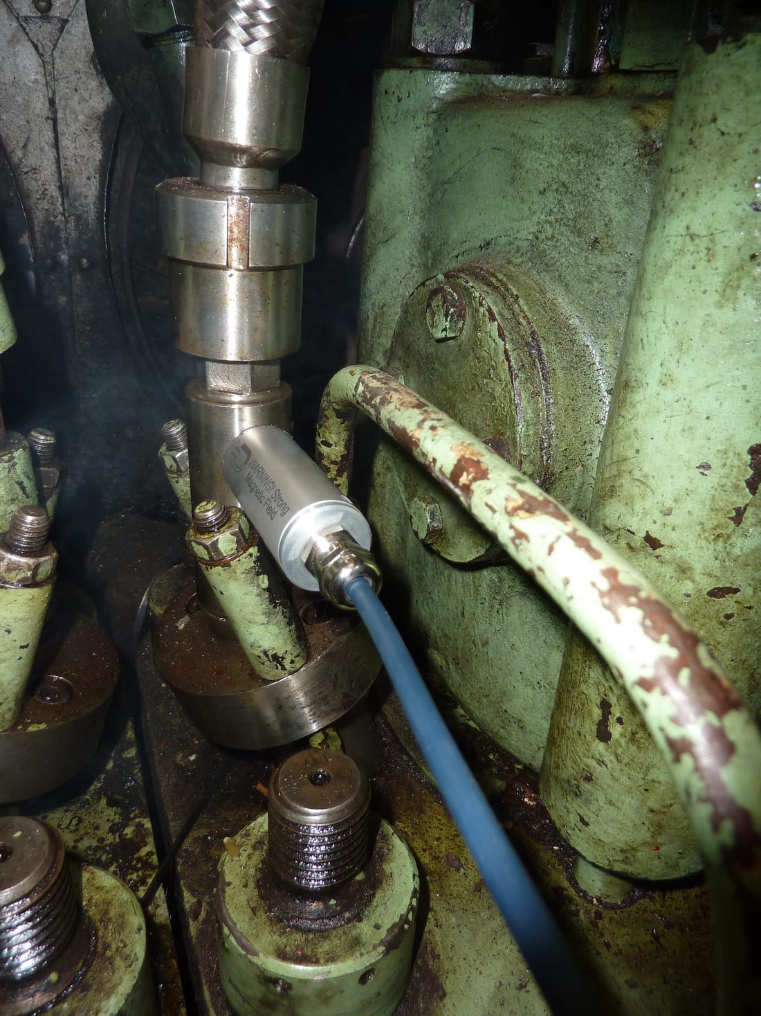
DS Acoustic sensor, magnetically mounted on a running engine, connected by its signal cable.
DS Acoustic sensor mounted on a running engine.
  • Frequency range 100–400 kHz
  • Magnetic mounting, repositioned between cylinders
  • One acoustic signal recorded per cylinder
  • Integral amplification and signal conditioning
Application

Diagnostic coverage

The combined measurement identifies the following conditions during normal operation, without engine disassembly.

  1. Combustion condition

    Deviation in peak pressure, compression pressure and injection timing relative to the engine builder reference values.

  2. Load distribution

    Uneven cylinder loading, identifying cylinders operating above or below the intended mean effective pressure.

  3. Mechanical condition

    Valve leakage, injector malfunction and abnormal mechanical events indicated through acoustic emission.

  4. Turbocharging and scavenge

    Turbocharger speed, scavenging pressure and air cooler performance assessed alongside combustion, identifying fouling and air-side restriction.

  5. Progressive deterioration

    Gradual compression loss or timing drift identified through repeated measurement and trend comparison.

Enquiries

Please provide the engine types concerned, the measurement or development requirement, and any existing equipment in use. This includes proposals for instruments outside pressure and acoustic emission measurement. A response will follow with scope, timing and price.